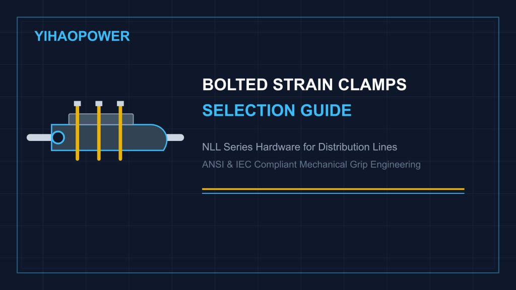
In overhead electricity distribution networks operating up to 35 kV, dead-end strain towers carry the full longitudinal mechanical tension of overhead conductors. To secure aluminum conductors steel reinforced (ACSR), all-aluminum conductors (AAC), or aluminum alloy conductors (AAAC) at terminal and angle poles, line engineers rely on heavy-duty strain clamps.
Among various strain hardware designs, bolted strain clamps (NLL series) offer an adaptable, re-usable, and non-destructive anchoring solution. By utilizing high-tensile U-bolts to press clamping waves against the conductor, NLL clamps provide dependable holding force without requiring specialized hydraulic crimping tools in the field.
This comprehensive engineering guide examines the mechanics of bolted strain clamps selection, holding strength formulas, material selection criteria, and field installation best practices for utility distribution grids.
1. Mechanical Holding Mechanics: Clamping Force vs. Conductor Deformation
The primary duty of a bolted strain clamp is to prevent conductor slippage under continuous mechanical tension, wind vibration, and ice accumulation. Unlike hydraulic compression strain clamps that permanently deform the aluminum strands, NLL series clamps rely on controlled friction and wave-geometry clamping.
The Physics of Friction-Based Holding
The total friction-based holding force (F_f) generated by a bolted strain clamp is calculated using the mechanical friction equation:
F_f = μ × N
Where:
- μ = Coefficient of friction between the inner clamp groove and the outer aluminum conductor strands.
- N = Total normal clamping force exerted by the tightened U-bolts across the wave-shaped clamping bed.
Preventing Conductor Strand Crushing
To achieve adequate holding strength without crushing the outer aluminum wire strands, NLL clamps feature engineered longitudinal wave grooves.
- Wave-Geometry Pressure Distribution: As the U-bolts are torqued, the wave-shaped body flexes the conductor slightly, creating multiple friction contact points along the clamp body.
- Slippage Strength Requirement: Properly installed bolted strain clamps achieve a holding strength equal to 95% or higher of the conductor’s rated ultimate tensile strength (RTS), ensuring zero strand slipping under maximum design loads.
2. Material Engineering: High-Strength Ductile Iron vs. Aluminum Alloy
Selecting the proper body material for bolted strain clamps depends directly on line voltage levels, mechanical load requirements, and electrical loss considerations.
- Ductile Iron Bodies (NLL Series): Cast from high-strength ductile iron (such as QT450-10), iron-body clamps deliver extreme mechanical tensile strength at cost-effective price points. All ferrous parts, including the clamp body, keeper plate, and U-bolts, are hot-dip galvanized according to ASTM A153 standards to resist outdoor atmospheric corrosion.
- Aluminum Alloy Bodies (NLL-A Series): Cast from high-strength, heat-treated aluminum alloy (A356/A356.2), aluminum-body clamps offer significant electrical advantages for high-current distribution lines. Because aluminum is non-magnetic, NLL-A clamps eliminate magnetic hysteresis and eddy current losses, reducing power line energy losses and heat buildup around the joint.
To review industry specifications for galvanized overhead distribution hardware, engineers can consult the ANSI C135.1 Standard for Galvanized Hardware.
3. Field Installation Protocol & Torque Control
Field installation errors are the leading cause of conductor slippage or strand damage in bolted strain clamps. Line crews should follow this mandatory 4-step installation protocol:
- Conductor Outer Diameter Alignment: Verify that the conductor outer diameter (OD) falls squarely within the marked range on the clamp body. Using an oversized clamp reduces effective clamping pressure, while an undersized clamp causes severe localized strand crushing.
- Apply Conductive Anti-Seize Paste: Coat the conductor section and inner clamp grooves with neutral conductive grease. The grease fills air gaps, seals out ambient moisture, and prevents fretting corrosion between strands under wind vibration.
- Sequential U-Bolt Tightening: Tighten the U-bolt hex nuts incrementally in an alternating sequence (front-back-front) using a calibrated torque wrench. Never fully torque one U-bolt leg before tightening the adjacent bolts, as this tilts the keeper plate and causes uneven pressure distribution.
- Jumper Tube Alignment: Ensure the conductor tail extends smoothly into the jumper tube section to allow unhindered jumper connection taps at dead-end towers.
4. Precision Blueprint Fabrication & Direct Sample Evaluation by YIHAOPOWER
As a specialized B2B manufacturer of distribution line fittings, YIHAOPOWER produces precision-cast NLL and NLL-A series bolted strain clamps built in accordance with international utility specifications.
The YIHAOPOWER Manufacturing Advantage
- Blueprint Precision: Custom groove radii, keeper plate geometry, and U-bolt lengths manufactured to match exact project drawing tolerances.
- Uniform Hot-Dip Galvanizing: Steel U-bolts, nuts, and iron bodies feature thick, uniform zinc coatings (averaging over 85 μm) for long-term rust protection in humid and coastal environments.
- 100% Pre-Shipment Trial Fitting: Every production lot undergoes manual U-bolt thread spinning, keeper plate alignment, and conductor groove clearance inspection before export packing.
- Direct Sample Shipping: We invite utility engineers, procurement managers, and EPC project teams to request direct sample deliveries shipped straight to your office or warehouse. Evaluate casting density, U-bolt thread fit, and trial-fit clamps on your physical conductor samples before placing volume orders.
Ready to inspect hardware samples or request technical drawings for your upcoming distribution grid tender? Contact YIHAOPOWER Team today for factory-direct quotes and direct sample arrangements.
Need Customized Hardware or Technical Datasheets?
Contact our team directly for instant quotations, CAD drawings, and samples.