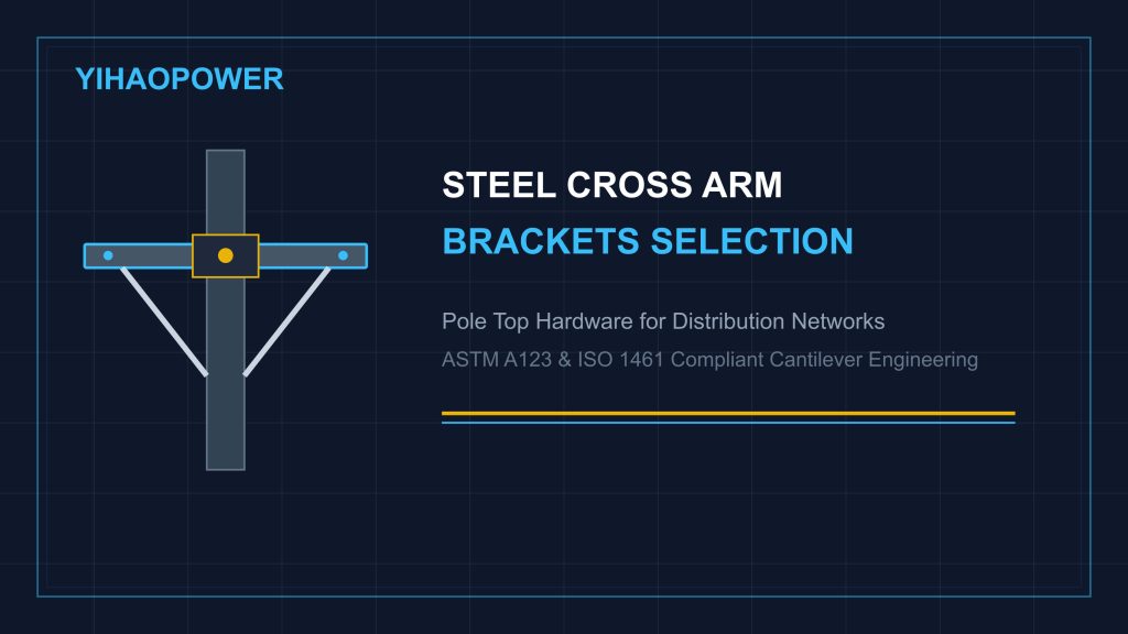
In overhead electricity distribution networks, utility poles rely on rigid structural supports to hold conductors, pin insulators, transformers, and cut-out switches in precise spatial alignment. Serving as the primary horizontal cantilever beam on wooden, concrete, and steel tubular poles, steel cross arm brackets must sustain substantial dynamic loads without undergoing permanent structural deflection.
Operating continuously in open outdoor environments, pole top hardware experiences severe mechanical stresses—including conductor deadweight, ice accumulation, wind pressure, and unbalanced line tension at angle poles. A failure in crossarm integrity can cause conductor sag misalignment, phase-to-phase flashover shorts, or catastrophic pole top collapse.
This technical guide examines the structural mechanics of steel cross arm brackets, section modulus calculations, hot-dip galvanizing standards, and field assembly practices for utility power infrastructure.
1. Mechanical Load Mechanics & Cantilever Deflection Calculations
Steel cross arm brackets function as structural cantilever or continuous beams anchored to the pole shaft using mounting plates, U-bolts, and diagonal braces. Engineering design requires balancing section modulus against peak dynamic loads.
Analyzing Cantilever Bending Moments
The maximum bending moment (M) acting on a cross arm bracket under vertical conductor loading is calculated using the cantilever beam formula:
M = F × L
Where:
- F = Total vertical downward load (N), combining conductor weight, insulator self-weight, and ice loading.
- L = Distance from the pole mounting attachment point to the outer insulator pin hole (m).
Flexural Stress & Section Modulus Criteria
To prevent permanent structural bending, the maximum bending stress (σ) must remain well below the allowable yield strength of the steel profile:
σ = M / Z ≤ [σ]
Where Z is the elastic section modulus of the chosen structural shape (structural channel steel or angle steel).
Structural Deflection Limits
According to international utility line design criteria, vertical elastic deflection at the crossarm tip under full design load should not exceed L / 200 (where L is the cantilever arm length). Excessive deflection alters conductor spacing, increasing the risk of conductor clashing during gusty wind storms.
2. Steel Profile Selection & Hot-Dip Galvanizing Standards
Selecting the appropriate structural steel profile and surface coating is critical to achieving multi-decade utility service lifespans.
Structural Steel Profile Options
- Structural Steel Channels (C-Channels / U-PN Profiles): Ideal for heavy distribution lines, transformer platform supports, and double-arming dead-end structures requiring high section modulus (Z-axis stiffness).
- Structural Steel Angles (Equal & Unequal Angle Bars): Commonly specified for light distribution crossarms, diagonal bracing struts, and pole top V-braces.
Corrosion Protection via Hot-Dip Galvanizing
Because crossarm brackets are elevated on pole tops exposed to industrial smog, high humidity, and coastal salt air, basic paint or electro-galvanizing is inadequate. Heavy steel crossarms must undergo full immersion hot-dip galvanizing in accordance with the ASTM A123 Standard for Structural Steel Coatings.
- Sacrificial Zinc Layer: The thermal diffusion process creates zinc-iron alloy layers covered by a pure zinc surface layer, delivering an average coating thickness of 85 μm to 100 μm (over 610 g/m²).
- Complete Internal & Slot Protection: Hot-dip galvanizing coats all pre-punched bolt holes, mounting slots, and cut edges, preventing localized internal rust pockets.
3. Field Mounting Protocol & Hardware Compatibility
Proper installation ensures that steel cross arm brackets maintain balanced load distribution across the pole structure. Field crews should adhere to these key mounting practices:
- Diagonal Bracing Integration: Long crossarms (exceeding 2.4 meters) require flat steel or angle iron diagonal braces forming a rigid triangular truss with the pole shaft. This dramatically reduces cantilever bending stress at the central mounting bolt.
- Double-Arming Fastening at Tension Poles: At dead-end or angle towers, utility designs utilize double-arming bolts (threaded rods with four nuts and square washers) to clamp two parallel crossarms on opposite sides of the pole, doubling the structural load capacity.
- Square Washer Stress Protection: Always install heavy curved or flat square steel washers between hex nuts and the pole face. Large plate washers distribute clamping torque over a wider area, preventing pole surface cracking or crushing.
4. Precision Blueprint Fabrication & Direct Sample Evaluation by YIHAOPOWER
As a specialized B2B manufacturer of pole line hardware and structural steel fittings, YIHAOPOWER fabricates custom steel cross arm brackets, braces, and pole top accessories engineered to exact project blueprints.
The YIHAOPOWER Manufacturing Advantage
- Exact Blueprint Punching & Slotting: Precision CNC hole punching, slotting, and length cutting executed prior to galvanizing to ensure zero raw edge exposure.
- Heavy Zinc Protection: Uniform hot-dip galvanizing meeting ASTM A123 and ISO 1461 specifications for multi-decade rust protection in harsh atmospheric environments.
- 100% Pre-Shipment Trial Fitting: Every production batch undergoes manual bolt hole alignment, slot clearance, and mounting bracket trial fitting before export packing.
- Direct Sample Shipping: We invite utility engineers, procurement managers, and EPC project teams to request direct sample deliveries shipped straight to your office or warehouse. Evaluate steel profile thickness, hole alignment, and zinc coating finish on your physical pole attachments before placing volume orders.
Ready to inspect hardware samples or request technical drawings for your upcoming distribution grid tender? Contact YIHAOPOWER Team today for factory-direct quotes and direct sample arrangements.
Need Customized Hardware or Technical Datasheets?
Contact our team directly for instant quotations, CAD drawings, and samples.